

PRODUCTESD Rule Check [Option]
Learn more about ESD Rule Check
What Is ESD Rule Check?
When a charged human body or other object comes into contact with electronic equipment, a sudden discharge of electricity can occur. This phenomenon is called ESD (Electrostatic Discharge) and can cause electronic equipment to malfunction or become damaged.
This feature consists of 10 check items covering signal routing, the proper placement of countermeasure components, and FG patterns. It identifies areas of a printed circuit board that are vulnerable to ESD and recommends countermeasures.
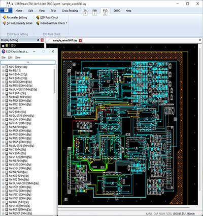
ESD Check Results
Key features include:
- ・Effective check items and thresholds validated by NEC laboratories based on expertise from companies in Japan and abroad.
- ・Enables ESD countermeasures at the early design stage, reducing the time required for countermeasures after prototype evaluation.
- ・Checks can be performed by importing CAD data and configuring only a few simple settings.
- ・Quickly identifies areas vulnerable to ESD, enabling prompt corrective action.
These features help users address ESD noise issues.
Example of Signal Routing Checks: Routing Across Plane Slots
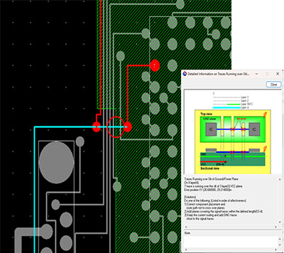
ESD Check Results (Routing Across Plane Slots)
When a signal trace passes over a slot or hole in a ground or power plane, the signal can be significantly affected by ESD noise.
This check detects such routing structures and issues an error warning.
Example of Countermeasure Component Placement Checks: Reset Line Check
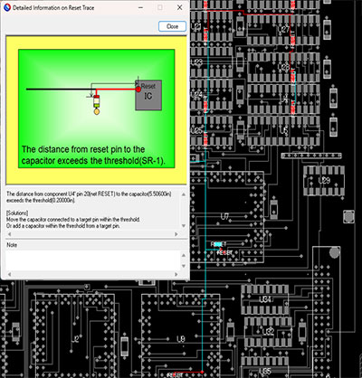
ESD Check Results (Reset Line Check)
To protect against ESD, countermeasure components such as capacitors are used on signal lines that are vulnerable to ESD noise. However, if these components are placed incorrectly, their noise suppression effectiveness may be reduced.
This check detects the placement of countermeasure components and issues an error warning when their locations are inappropriate.
Example of FG Pattern Checks: FG Pattern Check
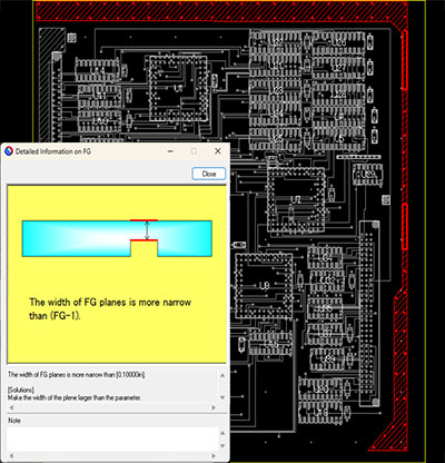
ESD Check Results (FG Pattern Check)
FG patterns provide a discharge path for ESD current. However, incorrect trace widths or interlayer via placement can cause noise to couple into signal lines and power or ground planes. The distance between FG patterns and power or ground planes also has a significant impact on noise coupling.
This check detects the structure of FG patterns and their distances from power and ground planes, issuing an error warning when potential problems are identified.